IEEE 1637-2010 pdf download.IEEE Guide to Select Terminations for Shielded Alternating-Current Power Cable Rated 5 kV – . 46 kV
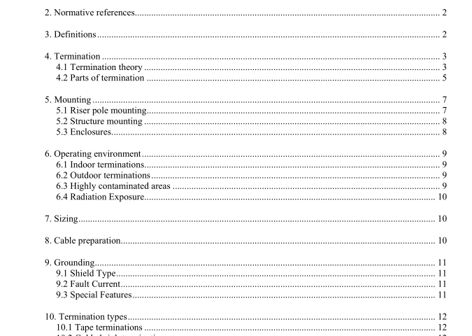
4. Termination
4.1 Termination theory
4.1.1 Shielded power cable configuration Shielded power cable is designed with two concentric conductors, one within the other separated by an insulating material.
The coaxial configuration forces the electric field energy associated with the alternating current (ac) into a symmetrical pattern. This configuration causes the total insulation to symmetrically contain the electric forces within the cable.
4.1.2 Dielectric field In all shielded power cable, an electric field exists when the conductor is energized. This dielectric field can be depicted graphically with the use of electrostatic flux lines and equi-potential lines (see Figure 1).
Electrostatic flux lines represent the electric stress between electrodes having different electric potential. Equi-potential lines represent points of equal potential between electrodes having different electric potential. They represent the radial voltage stresses in the insulation and their relative spacing indicates the magnitude of the voltage stress; the closer the lines, the higher the stress.
The coaxial configuration of a shielded power cable keeps the electric stresses symmetrical and under control as long as the cable components are left intact. To facilitate electric stress control at the end of a shielded-power cable, the insulation shield is removed axially for a distance sufficient to prevent interaction between the conductor and the insulation shield. When the insulation shield is ended, this leads to a concentration of electric stress at the shield terminus (see Figure 2).
Shielded-power cable terminations are designed to relieve this concentration of electric stress at the insulation shield terminus.
Figure 3 shows how this electric stress is overcome with a geometric type of electric stress control and Figure 4 shows how this electric stress is overcome with nonlinear types of electric stress control
4.2 Parts of termination A shielded power cable termination may be comprised of several elements. All terminations must have an electric stress control component. In addition, terminations may include the cable end seal, the connector, and electro-chemical track resistance on the surface of the termination between the insulation shield terminus and the cable conductor.
4.2.1 Cable end seal Class 1 terminations provide a seal to keep the environment out of the cable and when necessary, keep any gas, liquid, or semi-solid in the cable.
4.2.2 Connector When terminating a shielded power cable, a connection has to be made from the cable conductor to a piece of equipment. Termination connections used for power cables are most commonly compression connectors, but can be soldered, welded, bolted, or fastened by means of a set screw. It is imperative that prior to the installation of the connector, the cable conductor strands and connector be clean and free of contaminants and corrosion, including surface oxidation. This helps to make a solid, permanent connection. Regardless of what type of connection is used, all terminations require a connector that is listed as follows:
a) is compatible with the cable conductor metal
b) seals the power cable conductor, in combination with other termination components, from the entry of environmental contaminants into the conductor or the leakage of fluids, when present, from the conductor 4.2.2.1 Compression Connectors Compression connectors are either copper, aluminum, or a combination of both (bimetallic). Copper cable conductors can use either a copper connector (CU rated) or a dual rated aluminum connector (AL/CU rated).
Dual rated connectors often employ an intermediate metal between the copper and aluminum, usually in the form of a tin and/or zinc coating on the aluminum connector. Only aluminum connectors or dual rated connectors are applied to aluminum cable conductors. In some cases, a transition from aluminum to copper is needed.
For example, aerial connections, where an aluminum cable conductor connects to a copper conductor, require a transition connector. In this instance, a bimetal connector provides the transition.
A commonly used bimetal termination connector has an aluminum barrel with a copper stem. The transition area of the connector may have an intermediate metal at the interface or the interface may be spun welded to eliminate access of air and moisture to the metal junction.
This type of connector is sometimes referred to as a pin connector. Compression connectors for aluminum conductors require an inhibitor to fill the area between the conductor strands and the interior connector wall. Inhibitor generally comes preinstalled within the connector and is critical to its function. Inhibitor should not be removed from a connector. Inhibitors are intended to limit the formation of oxidation on the metal surfaces within the connector and on the surfaces of the cleaned conductor strands.
Inhibitors also serve to limit moisture intrusion into the connector and may include particles to enhance electrical contact between the metals. Because the inhibitor can contain conductive particles, excess inhibitor squeezed out of the connector should be cleaned away in the area between the end of the connector and the cable insulation. IEEE 1637 pdf download.IEEE 1637-2010 pdf download
IEEE 1637-2010 pdf download

Leave a Reply