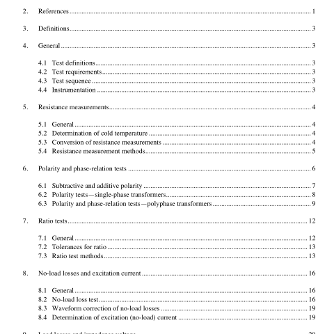
IEEE C57.12.91-2001 pdf download.IEEE Standard Test Code for Dry-Type Distribution and Power Transformers
3. Definitions Standard transformer terminology available in IEEE Std C57.12.80-1978 shall apply. Other electrical terms are defined in The Authoritative Dictionary of IEEE Standards Terms, Seventh Edition.
4. General
4.1 Test definitions Various types of tests such as routine , design , other , and conformance are defined in IEEE Std C57.12.80- 1978.
4.2 Test requirements A general summary of test requirements is included in Table 15 of IEEE Std C57.12.01-1998, which indicates by size (500 kVA and smaller, or 501 kVA and larger) which tests are normally considered routine , design , or other .
4.3 Test sequence See 10.1.5.4 for sequence of dielectric tests when lightning impulse tests are specified.
NOTE—If it is desired to minimize potential damage to the transformer during testing, the resistance, polarity, phase- relation, ratio, no-load-loss and excitation current, impedance and load-loss tests, and temperature-rise tests (when applicable) should precede dielectric tests. When this sequence is used, the beginning tests involve voltages and currents that are usually reduced compared to rated values, thus tending to minimize damaging effects to the transformer.
4.4 Instrumentation Although the figures in this standard show conventional meters, adequate digital-readout measuring devices and digital sampling techniques with computer calculations are considered satisfactory alternatives.
5. Resistance measurements
5.1 General Resistance measurements are of fundamental importance for the calculation of the I 2 R component of conductor losses, for the calculation of winding temperatures at the end of a temperature rise test, and as a base for assessing possible damage in the field. Cold-resistance measurements shall be taken on all phases of each primary and secondary winding on the rated tap connection. If a temperature rise test is to be performed, cold resistance measurements shall also be taken on all phases of each primary and secondary winding on the combination of connections and taps to be used for the temperature rise test. When transferring leads from one winding to another, the same relative polarity should be maintained with regard to the measuring leads and the transformer terminals.
The induction time for the measuring current to become stable should be noted during the cold-resistance measurements in order to ensure that sufficient time elapses for the induction effect to disappear before hot resistance readings are taken during the temperature rise tests. Cold-resistance measurements shall not be made on a transformer when it is located in drafts or when it is located in a room in which the temperature is fluctuating rapidly.
5.2 Determination of cold temperature
The cold temperature of the winding shall be determined as accurately as possible when measuring the cold resistance. The following precautions shall be observed.
The temperature of the windings for ventilated units shall be recorded as the average readings of several thermometers or thermocouples inserted between the coils. Care shall be taken to see that the measuring points of the thermocouples or thermometers are as nearly as possible in actual contact with the winding conductors. The temperature of the windings for sealed units shall be recorded as the average readings of several temperature sensors in contact with the tank and cover (see 11.8.6 and Figure 30).
It should not be assumed that the windings are at the same temperature as the surrounding air. To ensure that the windings are at ambient temperature, the following conditions shall be met immediately before taking cold-resistance measurements:
a) All internal temperatures measured by the internal temperature sensors shall not differ from ambient temperature by more than 2 ° C.
b) Tank surface temperatures for sealed units shall not differ from ambient temperature by more than 2 ° C.
c) Ambient temperature shall not have changed by more than 3 ° C for at least 3 h.
d) The transformer has been in a draft-free area for 24 h and neither voltage nor current has been applied to it for 24–72 h, depending on its size.IEEE C57.12.91 pdf download.IEEE C57.12.91-2001 pdf download
IEEE C57.12.91-2001 pdf download

Leave a Reply