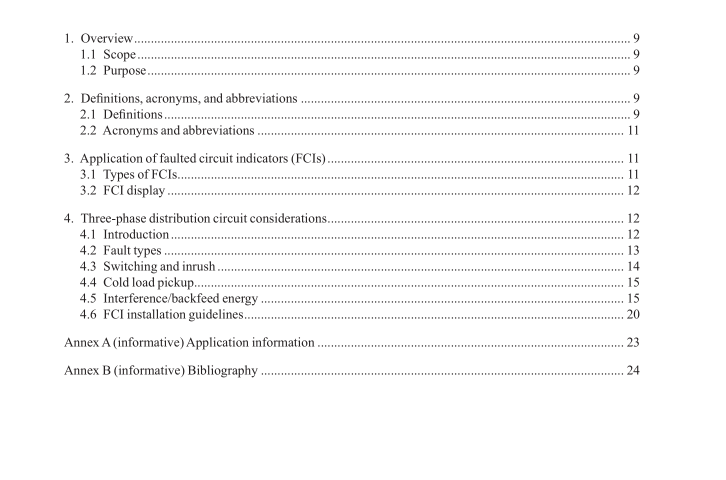
IEEE 1610-2016 pdf download.IEEE Guide for the Application of Faulted Circuit Indicators on Distribution Circuits
3. Application of faulted circuit indicators (FCIs) Underground and overhead FCIs are applied to monitor conductors at switchgear, transformers, junctions, cable dips, risers, etc. FCIs are attached to conductors, or test points, to sense for abnormally high currents typically associated with faults. FCIs trip with a visual, audible, radio, or remote indication when they have sensed conditions that are determined to indicate an overcurrent has passed its location.
FCIs located along the fault current path will trip to indicate a “FAULT,” while those that do not determine a fault current has passed its location will remain “NORMAL.” Operating personnel locate the faulted section between the last FCI dis- playing “FAULT” and the frst FCI displaying “NORMAL.” Circuits can be radial or looped. Looped circuits typically have an open point. When choosing the placement of FCIs, consideration between cost and customer reliability should be made. FCIs could be placed on both the incoming and outgoing cables of each transformer.
This would provide the most knowledge on where the fault is located since information would be available to diferentiate between cable faults and faults on the high voltage bus in the transformer. Evidence has shown that primary cable faults are much more prevalent than high voltage bus faults in trans- formers, switches, and junctions. To address the problem of cable faults, FCIs need only be placed on the outgoing cables of transformers.
Further reduction in the number of FCIs installed could be realized by locating them at every other transformer or less. However, for each reduction in the number of FCIs, the time to locate and isolate the faulted cable will increase. The customer outage time will also increase. Faulted circuit indicators are afected by many items including cold load pickup, inrush, switching surges, lightning, and power follow currents. Proper application is essential to proper operation. FCIs should avoid tripping on inrush, cold load pickup, and switching surges and operate before protective devices.
3.1 Types of FCIs
3.1.1 Manual reset Manual reset FCIs require an operator to check and reset each indicator after each fault event. The large variety of system conditions that occur on a distribution system makes it very difcult to create generalized applica- tion rules. Failure to reset the indicator can cause confusion for subsequent faults. Mechanical FCIs do not employ inrush restraint.
3.1.2 Automatic reset
FCIs are available with a variety of resetting means that return a tripped unit to its normal state. Automatic re- set types include reset by voltage, current, time, or combinations of each. Some FCIs with automatic reset can also be reset manually when desired to facilitate troubleshooting.
3.1.2.1 Current reset
Current reset FCIs will reset their indication when load current is sensed.
3.1.2.2 Voltage reset
Voltage resetting fault indicators are not afected by load current. Voltage resetting FCIs can be used on overhead or underground systems. There are several types of voltage resetting devices. The high and medium (primary) voltage resetting devices depend on the electrostatic feld surrounding a high or medium voltage cable or a separable connector’s capacitive test point for operating power. The electrostatic reset type requires that the cable be unshielded and a test point reset type requires the use of a test point type separable connector. The low (secondary) voltage resetting devices can only be applied wherever a secondary voltage is available and does not require a “test point type separable connector.” Minimum voltage levels and durations must be met for proper operation.
3.1.2.3 Time reset
Time reset FCIs will reset after a selected period of time regardless of voltage or current status. When choosing the length of time before reset, the time chosen should be long enough to allow operating personnel time to locate and isolate the fault. If some or all of the units reset before this is accomplished, confusing information as to the location of the fault exists. In contrast, choosing an excessively long time can also cause problems if there is a subsequent fault before the units have had a chance to reset.IEEE 1610 pdf download.IEEE 1610 pdf download
IEEE 1610-2016 pdf download

Leave a Reply