IEEE 1584-2018 pdf download.IEEE Guide for Performing Arc-Flash Hazard Calculations
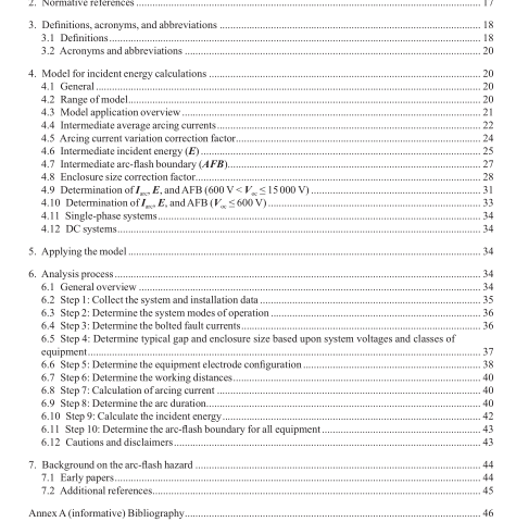
4. Model for incident energy calculations
4.1 General An empirically derived model is provided for incident energy calculations. Development of this model is discussed in Annex G. This annex provides more defnitions and explains the derivations of the coeffcients, variables, and terms used in the equations presented in 4.4 to 4.10. The equations in the model may be embedded in a spreadsheet or commercial software program, because it may be impractical to solve them by hand.
4.2 Range of model The following empirically derived model, based upon statistical analysis and curve-ftting programs as well as an understanding of electrical arc physics, is applicable for systems with the following parameter range:
— Voltages in the range of 208 V to 15 000 V, three-phase (line-to-line)
Tests were performed in laboratory conditions using selected open-circuit voltages (V oc ). While the model utilizes V oc , pre-fault voltage (system nominal voltage, utilization voltage, etc.) can be used for application of this model.
— Frequency of 50 Hz or 60 Hz
— Bolted fault current (rms symmetrical)
— 208 V to 600 V: 500 A to 106 000 A
— 601 V to 15 000 V: 200 A to 65 000 A
— Gaps between conductors
— 208 V to 600 V: 6.35 mm to 76.2 mm (0.25 in to 3 in)
— 601 V to 15 000 V: 19.05 mm to 254 mm (0.75 in to 10 in)
— Working distances greater than or equal to 305 mm (12 in) (see G.7.6 for details on the lower limit)
— Fault clearing time: No limit (see G.7.8 for more details)
— Enclosures tested (with open front end) as shown in the following table:
— Enclosure dimension limits (established using the enclosures from the 2002 version of this guide)
— Maximum height or width: 1244.6 mm (49 in)
— Maximum opening area: 1.549 m 2 (2401 in 2 )
— Minimum width: The width of the enclosure should be larger than four times the gap between conductors (electrodes).
— Electrode confgurations (see the defnition of electrode confguration in 3.1 and Figure G.1 through Figure G.5)
There are alternative calculation methods for system parameters that fall outside of the range of the model. However, no particular recommendation can be made because there are other application details such as bolted fault current levels, voltage, gap length, operating frequency, number of phases, types of faults, etc. The user is advised to properly research alternative calculation methods and their application viabilities.
4.3 Model application overview
The model for incident energy calculations has been divided into the following two parts depending on the ystem open-circuit voltage, V oc :
— Model for 600 V < V oc ≤ 15 000 V
— Model for 208 V ≤ V oc ≤ 600 V
Sustainable arcs are possible but less likely in three-phase systems operating at 240 V nominal or less with an available short-circuit current less than 2000 A.
The model uses a two-step process in which intermediate values of average arc current, incident energy, and arc-fash boundary are interpolated to determine fnal values. Correction factors for enclosure (box) size and arc current variation are applied to adjust the results.
A summary of the steps required to apply the model is provided as follows:
a) To determine the arcing current
1) Determine the applicable equipment electrode confguration based on 6.6.
2) If the system voltage is 600 V < V oc ≤ 15 000 V, use Equation (1) to fnd intermediate values at 600 V, 2700 V, and 14 300 V. Use Equation (16), Equation (17), Equation (18), and the guidance provided in 4.9 to fnd the fnal value of the arcing current.
3) If the system voltage is 208 V ≤ V oc ≤ 600 V, use Equation (1) to fnd the intermediate value (600 V only) and Equation (25) to fnd the fnal value. Guidance for the determination of the fnal arcing current is provided in 4.10.
b) Determine the arc duration or fault clearing time using the arcing current determined in step a). Guidance for determining the arc duration is provided in 6.9.
c) To determine the incident energy
1) Determine the enclosure size correction factor using the guidance provided in 4.8.4.IEEE 1584 pdf download.IEEE 1584-2018 pdf download
IEEE 1584-2018 pdf download

Leave a Reply