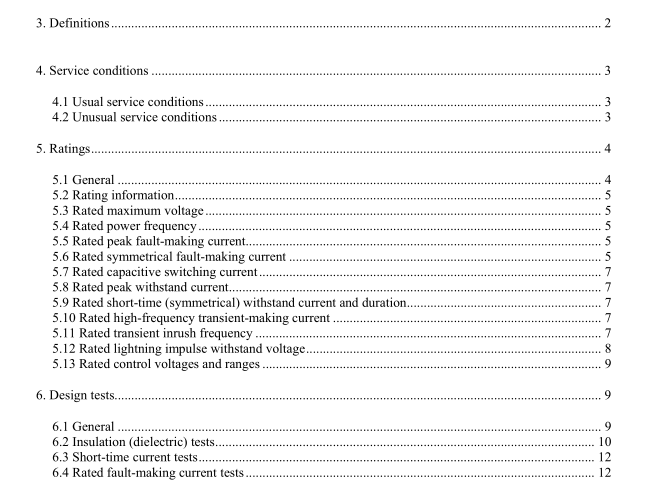
IEEE C37.66-2005 pdf download.IEEE Standard Requirements for Capacitor Switches for AC Systems (1 kV to 38 kV)
5.7 Rated capacitive switching current The preferred values for the rated capacitive switching current of capacitor switches are shown in Column 3 of Table 2 and Table 3.
5.7.1 Conditions of continuous capacitive current rating
a) Capacitor switches are used under the usual service conditions defined in 4.1.
b) Current ratings shall be based on the total temperature limits of the materials used for such parts. A temperature rise reference is given to permit testing at reduced ambient.
c) Capacitor switches installed in open-air racks shall have their ratings based on a 40 °C ambient temperature. Capacitor switches installed in enclosures shall have their ratings based on the ventilation of such enclosures and a 40 °C ambient temperature outside the enclosure.
5.7.2 Limits of observable temperature rise At rated current, the observable hottest-spot temperature rise above ambient and the temperature of each of the various parts shall not exceed those listed in Table 4.
5.8 Rated peak withstand current The preferred values for the rated peak withstand current at 60 Hz of capacitor switches are shown in Column 6 of Table 2 and Table 3. The preferred values for the rated peak withstand current, expressed in peak amperes, are defined as a multiple of the symmetrical fault-making current shown in Column 5 of Table 2 and Table 3. Lower values than the ones shown in Column 6 of Table 2 and Table 3 are acceptable for 50 Hz applications. For switches rated according to Table 2, the multiplication factor of the symmetrical current is 2.45 for 50 Hz. For switches rated according to Table 3, the multiplication factor is 2.55 for 50 Hz.
5.9 Rated short-time (symmetrical) withstand current and duration The preferred values for the rated short-time (symmetrical) withstand current of capacitor switches are shown in Column 7 of Table 2 and Table 3. The rated short-time withstand current durationis 1 s.
5.10 Rated high-frequency transient-making current The preferred values for the rated high-frequency transient-making current of capacitor switches are shown in Column 8 of Table 2 and Table 3. 5.11 Rated transient inrush frequency The preferred values for the rated transient inrush frequency of capacitor switches are shown in Column 9 ofTable 2 and Table 3.
The rated transient inrush frequency is the highest frequency the switch shall be required to close at 100% rated high-frequency transient-making current shown in Column 8 of Table 2 and Table 3.
For application at less than 100% of rated high-frequency transient-making current, the product of the actual high- frequency transient-rmaking current and the actual transient inrush frequency shall not exceed the product of the rated high-frequency transientmaking current and the rated transient inrush frequency. Refer to Annex B for additional details and application examples.
6. 6.1 Design tests General
Capacitor switches shall be capable of meeting the design tests described in 6.2 through 6.10, inclusively. Once made, the design tests need not be repeated unless the design is changed so as to modify the performance characteristics of the switch.
6.1.1 Condition of switch to be tested
The switch shall be new and in good condition, and tests shall be applied before the switch is put into commercial service, unless otherwise speified.
6.1.2 Mounting of specimen
The switch shall be mounted on its hanger or mounting means in a manner closely approximating the normal service conditions for which it is designed.
6.1.3 Grounding of specimen
The housing or hanger, or both, and all groundable parts shall be grounded by a lead or leads attached to the appropriate ground terminal points in a manner not to decrease the withstand voltage.
6.1.4 Power frequency
The frequency of the power supply voltage shall be the rated power frequency +2%。A sine wave of acceptable commercial standards shall be applied. Such a wave shape is defined in 6.1.1 of IEEE Std 4-1995. The following test guidelines apply for rated power frequency:
a) Tests at 60 Hz may be considered to prove the breaking characteristics at 50 Hz.
b) Tests at 50 Hz may be considered to prove the characteristics at 60 Hz when the specified voltage across the switch is not less during the first 8.3 ms than it would be during a test at 60 Hz and the making curent is not less than that required for the 60 Hz test. This means that Vson/V6oHz= 1.3. Ifa restrike occurs after 8.3 ms, due to a higher instantancous voltage than it would be during a 60 Hz test at the specified voltage, the test duty should be repeated at 60 Hz.
6.2 Insulation (dielectric) tests Capacitor switches shall be capable of withstanding, without damage, the following test voltages when tested in accordance with 6.1 and as outined in 6.2.1 through 6.2.5.
6.2.1 Electrical connections Electrical connections shall be made by means of bare wire inserted in or appropriately bolted to each terminal depending on the terminal interface design. These wires shall project in such a manner as not to decrease the withstand value. IEEE C37.66 pdf download.IEEE C37.66-2005 pdf download
IEEE C37.66-2005 pdf download

Leave a Reply