IEEE 1770-2021 pdf download.IEEE Recommended Practce for the Usage of Terms Commonly Employed in the Field of Large- Signal Vector Network Analysis
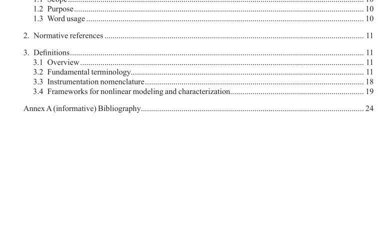
1. Overview
This recommended practice defines a select set of common terms in microwave network analysis.
1.1 Scope
This recommended practice defines common terms in large-signal vector network analysis. Some fundamental terms used in small-signal vector network analysis that are also commonly used in large-signal vector network analysis are covered as well.
1.2 Purpose
The purpose of this recommended practice is to provide guidance to professionals in the field of large-signal vector network analysis in employing terms to describe common large-signal-vector-network-analysis concepts and in employing fundamental terms commonly borrowed from small-signal vector network analysis that are also often used in large-signal vector network analysis.
1.3 Word usage
The word shall indicates mandatory requirements strictly to be followed in order to conform to the standard nd from which no deviation is permitted (shall equals is required to). 1,2
The word should indicates that among several possibilities one is recommended as particularly uitable,without mentioning or excluding others; or that a certain course of action is preferred but not ecessarily required (should equals is recommended that).
The word may is used to indicate a course of action permissible within the limits of the standard (may equals is permitted to).
The word can is used for statements of possibility and capability, whether material, physical, or causal (can quals is able to).
2. Normative references
There are no normative references in this recommended practice.
3. Defnitions
3.1 Overview
The definitions for the common terms listed in this recommended practice should be used in discussions of large-signal and small-signal vector network analysis. The definitions address fundamental terminology,instrumentation nomenclature, and frameworks for nonlinear modeling and characterization commonly used in the field. Some common terms are also defined for completeness. The IEEE Standards Dictionary Online should be consulted for terms not listed below.
3.2 Fundamental terminology
3.2.1 Transmission-line equivalent-circuit parameters
Transmission-line equivalent-circuit parameters consist of the per-unit-length series resistance R, series inductance L, shunt conductance G, and shunt capacitance C that make up the distributed circuit model hown in Figure 1.
NOTE 1—The transmission line associated with these equivalent-circuit parameters is said to be lossless if R and G are zero; uniform if L, C, R, G are not functions of z and nonuniform if they are; dispersive if L, C, R, G are functions of frequency and nondispersive if they are not; and nonlinear if L, C, R, G are non-constant functions of voltage, current, charge, or fux, as appropriate, and linear if they are constant. In addition, the transmission line is said to be ideal if it is lossless, uniform, nondispersive, and linear and nonideal otherwise.
NOTE 2—By convention, the equivalent-circuit model applies to a two conductor quasi-TEM guided structure for electromagnetic waves. A very important case in practice is one in which there are losses, both in the series path that represents the conductors of the line, as well as in the shunt path that represents leakage in the dielectric that separates the two conductors. For the linear sinusoidal steady state case, the series path consists of a distributed impedance Z and the shunt path consists of a distributed admittance Y expressible as shown in Equation (1) for the linear case of the equivalentcircuit model given in Figure 1:
Z = R + jωL, Y = G + jωC
NOTE 3—Again for the linear sinusoidal steady state case, to be consistent with non-TEM transmission lines (e.g.,rectangular waveguide), the transmission-line equivalent-circuit parameters should be defned from both the propagation constant y that derives from the Maxwell electromagnetic feld equations, and the characteristic impedance Z 0 of that transmission line determined by the chosen circuit theory with Equation (2) and Equation (3):
Z = R + jωL = γ Z 0.IEEE 1770 pdf download.IEEE 1770-2021 pdf download
IEEE 1770-2021 pdf download

Leave a Reply