IEEE 303-2004 pdf download.IEEE Recommended Practice for Auxiliary Devices for Rotating Electrical Machines in Class I, Division 2 and Zone 2 Locations
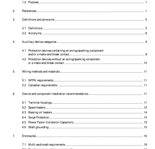
4. Auxiliary device categories
For installation requirements, auxiliary devices generally fall in one of two categories:
1) Devices containing an arcing/sparking component and/or a make-and-break contact
2) Devices that do not contain an arcing/sparking component or a make-and-break contact.
4.1 Protection devices containing an arcing/sparking component and/or a make and-break contact
Devices containing an arcing/sparking component and/or a make-and-break contact are installed either inside or outside of the machine housing. Examples of devices included in this category are:
a) Commutators or slip-rings
b) Bearing temperature switches or relays
c) Certain types of winding temperature sensors
d) Vibration switches
e) Air filter differential pressure switches
f) Zero speed switches
g) Brush or switch type encoders, resolvers or tachometers
h) Leak detector switches or relays
i) Other types of relays or switches
j) Fuses
k) Pre-start purging panels
l) Shaft grounding brushes.
These devices must be installed following acceptable protection techniques (i.e. those suitable for the application, Class, Group [where applicable], Division or Zone). The enclosure should be designed for the stated environmental conditions.
4.1.1 Protection techniques
4.1.1.1 Class I, Division 2 techniques
For Class I, Division 2 locations, acceptable protection techniques include:
a) Explosion-proof enclosures (approved for Class I, Division 1 or Division 2). CSA C22.2 No. 30 M1986 (R1999); and UL 1203-2000.
b) Contacts immersed in oil, UL 698-1995.
c) Intrinsically safe circuits, CAN/CSA C22.2 No. 157-92 (R2002), NFPA 70-2005, Articles 500 and 504, and UL 913-2002.
d) Non-incendive circuits, NFPA 70-2005; Article 501.3(B)(1)(c); CSA C22.2 No. 213-M1987 (R1999); and UL 1604-1994.
e) Purged/pressurized enclosures, NFPA 496-2003.
f) Contacts mounted in an hermetically sealed chamber. CSA C22.2 No. 213-M1987 (R1999); and UL 1604-1994.
g) Any Class I, Zone 0, 1 or 2 technique.
4.1.1.2 Class I, Zone 2 techniques
For Class I, Zone 2 locations, acceptable protection techniques include:
a) Flameproof enclosures “d”. AS/NZS 60079.1:2000; CENELEC EN50018-2000; CAN/CSA-E60079-1:02; IEC 60079-1:2001; and UL 60079-1-2002.
b) Purged and Pressurized “p”. AS/NZS 60079.2:2002; CENELEC EN 50016-1996; CAN/CSA-E60079-2:02; IEC 60079-2:2001; and NFPA 496-2003.
c) Intrinsically safe “i”. AS/NZS 60079.11:2000; CENELEC EN 50020-2002; CAN/CSA-E60079-11:02; IEC 60079-11:1999; and UL 60079-11 -2002.
d) Type “n” protection. CENELEC EN 50021-1999; CAN/CSA-E60079-15:02; IEC 60079-15:2001;and UL 60079-15-2002.
e) Oil immersion “o”. AS/NZS 60079.6:2000; CENELEC EN 50015-1998; CAN/CSA-E60079-6:02;IEC 60079-6:1995; and UL 60079-6-2002.
f) Increased Safety “e”. AS/NZS 60079.7:2002; CENELEC EN 50019-2000; CAN/CSA-E79-7-95;IEC 60079-7:2001; and UL 60079-7-2002.
g) Encapsulation “m”. CENELEC EN 50028-1987; CAN/CSA-E79-18-95; IEC 60079-18:1992; and UL 60079-18-2002.
h) Powder filling “q”. AS/NZS 60079.5:2000; CENELEC EN 50017-1998; CAN/CSA-E60079-5:02;IEC 60079-5:1997; and UL 60079-5-2002.
i) Any Class I, Division 1 or 2 technique.
j) Any Class I, Zone 0 or 1 technique.
4.2 Protection devices without an arcing/sparking component or a make-and-break contact
Devices without an arcing/sparking component or a make-and-break contactinstalled either inside or outside of the machine housing may be of the general-purpose type unless other environmental considerations dictate the use of a specific enclosure especially designed for operation in that environment. Examples of devices included in this category are:
a) Resistance temperature detectors (RTDs)
b) Space heaters
c) Bearing oil heaters
d) Brake solenoids
e) Solid state type speed transducers (pulse generators, encoders, resolvers and tachometers)
f) Non-contacting shaft vibration probes and their oscillator/demodulators (drivers)
g) Current or potential transformers
h) Partial Discharge couplers
i) Surge capacitors
j) Gapless type arresters
k) Other devices that do not arc during normal operation.
5. Wiring methods and materials
5.1 NFPA requirements
5.1.1 Internal The general and specific rules of NFPA 70-2005 with regard to wiring methods are not intended to apply to internal wiring of rotating electrical machines. Refer to NFPA 70-2005, Article 300.1(B). It is suggested that the user notify the manufacturer of any specific environmental considerations that dictate the use of a specific wiring material specifically designed for operation in that environment.
5.1.2 External For Class I, Division 2 locations, device wiring located outside the machine should meet the requirements of NFPA 70-2005, Article 501, pertaining to wiring methods and installations. For Class I, Zone 2 locations, device wiring located outside the machine should meet the requirements of NFPA 70-2005, Article 505.15. Intrinsically safe wiring should meet the requirements of NFPA 70-2005, Article 504.
5.2 Canadian requirements Class I, Division 2 installations are covered in CSA C22.1-02 Annex J18-150 to J18-178. Class I, Zone 2 location installations are covered in CSA C22.1-02, paragraphs 18-150 to 18-187.IEEE 303 pdf download.IEEE 303-2004 pdf download
IEEE 303-2004 pdf download

Leave a Reply