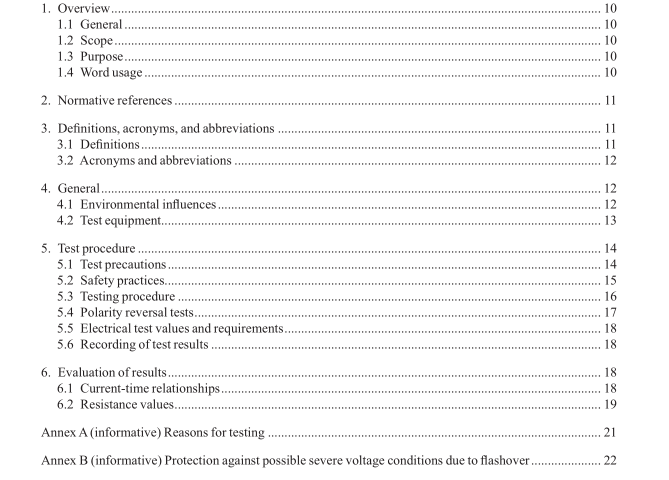
IEEE 400.5-2021 pdf download.IEEE Guide for Field Testng of DC Shielded Power Cable Systems Rated 5 kV and Above with High Direct Current Test Voltages.
4. General
4.1 Environmental infuences
4.1.1 Temperature
Temperature of the insulation may affect the voltage distribution and the dielectric strength of the cable. It is recommended that the temperature of the cable during a dc test on a dc cable will be within the operating temperature range of the cable. The ambient temperature, barometric pressure, and the humidity shall be recorded at the time of the test and with each subsequent test.
4.1.2 Atmospheric conditions
High humidity and conditions favoring condensation on exposed surfaces can affect the leakage current measured to a marked degree. Contamination of termination surfaces can greatly increase conduction or leakage current and reduce flashover levels. Relative air density affects the measurement of a test voltage by use of rod gaps and may also affect the flashover voltage of cable terminations. At elevations higher than 1000 m (3280 ft), additional insulation and clearance may be required to withstand both working voltages and the prescribed test voltages. If excessive corona or air discharges exist during a test, a reduced test voltage due to transient voltage dips may result and high leakage current readings may be present.
4.1.3 Extraneous electric felds
Although field tests on cable are often made in the vicinity of energized equipment, extraneous electrical fields usually will have little influence on direct voltage test results as long as the voltage measurement circuit is well shielded. A simple test to see the influence on the measurement system can be made by ungrounding the test system prior to energization and observing any indications on the test system instrumentation on the lowest metering range. It is always important to maintain adequate clearances for the dc test voltages anticipated also taking into consideration the recommended clearance for the energized adjacent circuits. Care should always be taken to help avoid sharp connections on the high-voltage circuit to maintain low electric feld values on test terminals and to reduce corona discharges
4.2 Test equipment
4.2.1 HVDC test equipment The test voltage source should do the following:
— Provide the maximum test voltage required plus some margin.
— Provide means for reversing test voltage polarity, if required, according to the application intended
— Provide a means of increasing voltage continuously or in small steps.
— Have a current capability suffcient to charge the test object in a reasonable time.
— Maintain a ripple factor as defned in IEEE Std 4™ 12 of less than 3%. Normally the capacitance of the test object reduces the ripple voltage of the dc source to low levels.
— Provide a suffciently powerful source to keep voltage dips during transient current pulses to a value of less than 10% of the set voltage. Care should always be taken to help avoid strong corona discharges from high-voltage connections that cause transient current pulses.
— Provide voltage and current instrumentation that meet the requirements of IEEE Std 4. Ammeters used to measure leakage current should have a low range that can resolve currents of 10 µA to 100 µA. An ammeter of suffcient range and scale should be provided to measure the leakage current accurately. Often, ammeters are provided with guard circuits to isolate the measurement of the current through the test object from stray leakage current.
4.2.2 Power supply
A well-stabilized power supply for the HVDC generator is essential. Minor variations in the input mains voltage or the test voltage power supply can cause major variations in the output current indication. The test voltage should remain stable to within 3% during the test time.
4.2.3 Discharge resistor
A resistor, used to discharge the load capacitance, with a resistance not less than 5000 Ω/kV of test voltage and adequate energy and power rating is highly recommended to be used to discharge the cable system after testing and reduce the voltage to zero. This resistor should be designed to withstand the full test voltage without flashover and to handle the discharge energy without overheating. Different types of resistors may be used, which include variable resistance water resistors, silicon carbide or block resistors and wire wound resistors. For safety reasons, for testing high voltage and ultra-high voltage dc cable systems, the high voltage discharge resistors should be connected by remote means.IEEE 400.5 pdf dwonload.IEEE 400.5-2021 pdf download
IEEE 400.5-2021 pdf download

Leave a Reply