IEEE 421.5-2005 pdf download.IEEE Recommended Practice for Excitation System Models for Power System Stability Studies
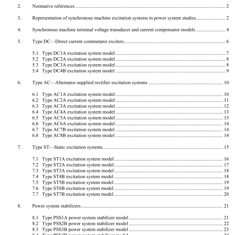
4. Synchronous machine terminal voltage transducer and current compensator models Several types of compensation are available on most excitation systems.
Synchronous machine active and reactive current compensation are the most common. Either reactive droop compensation and/or line-drop compensation may be used, simulating an impedance drop and effectively regulating at some point other than the terminals of the machine.
The impedance or range of adjustment and type of compensation should be specified. Droop compensation takes its name from the drooping (declining) voltage profile with increasing reactive power output on the unit. Line-drop compensation, also referred to as transformer-drop compensation, refers to the act of regulating voltage at a point partway within a generator’s step-up transformer or, less frequently, somewhere along the transmission system. This form of compensation produces a rising voltage profile at the generator terminals for increases in reactive output power.
A block diagram of the terminal voltage transducer and the load compensator is shown in Figure 4-1. These model elements are common to all excitation system models described in this document. It is realized that, for some systems, there may be separate and different time constants associated with the functions of voltage sensing and load compensation.
The distinction is not recognized in this model, in which only one time constant, T R , is used for the combined voltage sensing and compensation signal. Single-phase voltage and current sensing will, in general, require a longer time constant in the sensing circuitry to eliminate ripple. When load compensation is not employed ( R C = X C = 0), the block diagram reduces to a simple sensing circuit. The terminal voltage of the synchronous machine is sensed and is usually reduced to a dc quantity. While the filtering associated with the voltage transducer may be complex, it can usually be reduced, for modeling purposes, to the single time constant T R shown. For many systems, this time constant is very small and provision should be made to set it to zero.
The terminal voltage transducer output, V C , is compared with a reference that represents the desired terminal voltage setting, as shown on each of the excitation system models. The equivalent voltage regulator reference signal, V REF , is calculated to satisfy the initial operating conditions. It will, therefore, take on a value unique to the synchronous machine load condition being studied.
The resulting error is amplified as described in the appropriate excitation system model to provide the field voltage and subsequent terminal voltage to satisfy the steady-state loop equations. Without load compensation, the excitation system, within its regulation characteristics, attempts to maintain a terminal voltage determined by the reference signal.
When compensation is desired, the appropriate values of R C and X C are entered. In most cases, the value of R C is negligible. The input variables of synchronous machine voltage and current must be in phasor form for the compensator calculation. Care must be taken to ensure that a consistent pu system is utilized for the compensator parameters and the synchronous machine current base.
This type of compensation is normally used in one of the following two ways:
a) When synchronous machines are bused together with no impedance between them, the compensator is used to create artificial coupling impedance so that the machines will share reactive power appro- priately. This corresponds to the choice of a regulating point within the synchronous machine. For this case, R C and X C would have positive values.
b) When a single synchronous machine is connected through significant impedance to the system, or when two or more machines are connected through individual transformers, it may be desirable to regulate voltage at a point beyond the machine terminals. For example, it may be desirable to com- pensate for a portion of the transformer impedance and effectively regulate voltage at a point part way through the step-up transformer. For these cases, R C and X C would take on the appropriate neg- ative values.IEEE 421.5 pdf download.IEEE 421.5-2005 pdf download
IEEE 421.5-2005 pdf download

Leave a Reply