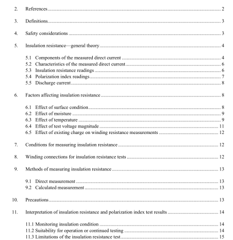
IEEE 43-2000 pdf download.IEEE Recommended Practice for Testing Insulation Resistance of Rotating Machinery
3. Definitions For the purposes of this recommended practice, the following terms and definitions apply. The IEEE Dictio- nary of Electrical and Electronics Terms should be referenced for terms not defined in this clause.
3.1 absorption (polarization) current ( I A ) : A current resulting from molecular polarizing and electron drift, which decays with time of voltage application at a decreasing rate from a comparatively high initial value to nearly zero, and depends on the type and condition of the bonding material used in the insulation system.
3.2 conduction current ( I G ) : A current that is constant in time, that passes through the bulk insulation from the grounded surface to the high-voltage conductor, and that depends on the type of bonding material used in the insulation system.
3.3 electroendosmosis effect : A phenomenon occasionally observed, more often on older windings, when, in the presence of moisture, different insulation resistance values may be obtained when the polarity of the tester leads are reversed. Typically for older wet windings, the insulation resistance for reverse polarity, where the ground lead is connected to the winding and the negative voltage lead to ground, is much higher than for normal polarity.
3.4 insulation resistance ( IR t ) : The capability of the electrical insulation of a winding to resist direct cur- rent. The quotient of applied direct voltage of negative polarity divided by current across machine insulation, corrected to 40 ° C, and taken at a specified time ( t ) from start of voltage application. The voltage application time is usually 1 min ( IR 1 ) or 10 min ( IR 10 ), however, other values can be used. Unit conventions: values of 1 through 10 are assumed to be in minutes, values of 15 and greater are assumed to be in seconds.
3.5 geometric capacitive current ( I C ) : A reversible current of comparatively high magnitude and short duration, which decays exponentially with time of voltage application, and which depends on the internal resistance of the measuring instrument and the geometric capacitance of the winding.
3.6 polarization index ( P.I. t 2 /t 1 ) : Variation in the value of insulation resistance with time. The quotient of the insulation resistance at time ( t 2 ) divided by the insulation resistance at time ( t 1 ). If times t 2 and t 1 are not specified, they are assumed to be 10 min and 1 min, respectively. Unit conventions: values of 1 through 10 are assumed to be in minutes, values of 15 and greater are assumed to be in seconds (e.g., P.I. 60/15 refers to IR 60s / IR 15s ).
3.7 surface leakage current ( I L ) : A current that is constant with time, and which usually exists over the sur- face of the end-turns of the stator winding or between exposed conductors and the rotor body in insulated rotor windings. The magnitude of the surface leakage current is dependent upon temperature and the amount of conductive material, i.e., moisture or contamination on the surface of the insulation.
4. Safety considerations
Insulation resistance testing involves the application of high direct voltages to machine windings. These windings have capacitive and inductive properties that can lead to hazards that may not be readily apparent. It is not possible to cover all safety aspects in this recommended practice and test personnel should consult IEEE Std 510-1983; 6 ASTM F855-97e1; manufacturers’ instruction manuals; and union, company, and gov- ernment regulations.
Before any testing is conducted, the winding insulation must be discharged. It is not safe to begin testing before the discharge current is zero and there is no discernible return voltage (less than approximately 20 V) after the ground is removed. After completion of the test, the winding should be discharged through a suit- able resistor, sized to limit the instantaneous current to 1 A. A minimum discharge time, which is equal to four times the voltage application duration, is recommended. This time interval is based on the R (resistive), L (inductive), C (geometric capacitive), and absorptive characteristics of the circuit during charging (time of the application of the voltage) and discharging (elapsed time since the removal of the voltage source and subsequent grounding of the winding under test). It is important to remember that the testing is not complete until the winding is discharged and there is no discernible voltage. It is recommended that subsequent ac high-potential testing not be conducted until the winding is fully discharged.IEEE 43 pdf download.IEEE 43-2000 pdf download
IEEE 43-2000 pdf download

Leave a Reply