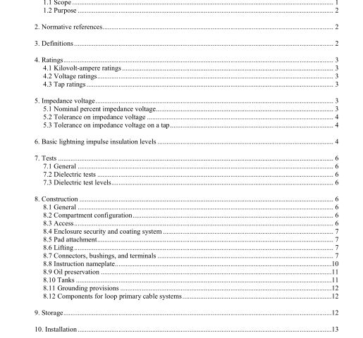
IEEE C57.12.34-2015 pdf download.IEEE Standard Requirements for Pad-Mounted, Compartmental-Type, Self-Cooled, Three-Phase Distribution Transformers, 1 0 MVA and Smaller; High-Voltage, 34.5 kV Nominal System Voltage and Below; Low-Voltage, 1 5 kV Nominal System Voltage and Below
7. Tests
7.1 General
Except as specified in 7.2 and 7.3 of this standard, tests shall be performed as specified in IEEE Std C57.12.00 and IEEE‖ Std‖ C57.12.90™.
7.2 Dielectric tests For wye-wye connected transformers, no applied voltage test is required on a winding greater than 600 V. An induced voltage test shall be performed as specified in IEEE Std C57.12.90. The voltage induced between the line terminals of a winding with a voltage greater than 600 V and the ground shall be the lower of the following values:
a) 3.46 times the rated winding voltage plus 1000 V, or
b) The applied voltage test values provided in Table 5 of IEEE Std C57.12.00-2006 2010, Table 4. When high or low-voltage terminations are used that fall under IEEE Std 386-2006, they may not be suitable for chopped wave testing; therefore, when terminations that conform to IEEE Std 386-2006 are used (bushing wells, 600 A integral bushings, etc.) chopped wave tests are not required.
7.3 Dielectric test levels Dielectric test levels shall be in accordance with the distribution levels in Table 5 of 4 of IEEE Std C57.12.00-20062010.
8. Construction
8.1 General
A pad-mounted, compartmental-type transformer shall consist of a tank with high-voltage and low- voltage cable terminating compartments, as shown in this standard. The compartment shall be separated by a barrier of metal or other rigid material.
8.2 Compartment configuration The high-voltage and low-voltage compartments shall be located side-by-side on one side of the transformer tank. When viewed from the front, the lower-voltage compartment shall be on the right.
8.3 Access Each compartment shall have a door so constructed as to provide access to the higher-voltage compartment only after the door to the lower-voltage compartment has been opened. There shall be one or more additional captive fastening devices that must be disengaged before the higher voltage door can be opened.
If the lower-voltage compartment has exposed live parts that are over 600 V, a non-hygroscopic barrier shall be placed so as to require its removal or opening before access to the lower-voltage compartment can be attained. Where the lower-voltage compartment door is of a flat panel design, the door shall have three-point latching with a handle provided for a locking device.
The compartment doors shall be of sufficient size to provide adequate operating and working space when removed or open. The doors shall either be equipped for latching in the open position or designed for manual removal.
8.4 Enclosure security and coating system
The transformer tank and compartment‖ shall conform to IEEE Std C57.12.28™ or IEEE Std C57.12.29™ [B2] 4 , as appropriate, and be so constructed as to limit disassembly, breakage, and prying open of any doors, panels, and sills when the doors are in the closed and locked position.
8.5 Pad attachment
The bottom edges of the compartments shall be so constructed as to provide for the use of hold- down devices which are accessible only from the inside of the compartments.
8.6 Lifting
The construction of the unit shall be such that it can be lifted, skidded, or slid, or any combination of these, into place on the mounting surface without disturbing the high-voltage or low-voltage cables.
a) Jack bosses or jacking facilities shall be provided on the tank for transformers rated 500 kVA or larger. The vertical clearance for a jack shall be 38 mm (1.5 in) minimum and, 165 mm (6.5 in) maximum.
b) The transformer shall be arranged for rolling in two directions; parallel to and at right angles to one side of the transformer.
c) The transformer shall be provided with lifting provisions permanently attached and arranged on the tank to provide a distributed balanced lift in a vertical direction for the completely assembled transformer and shall be designed to provide a safety factor of five when the horizontal angle of loading on the lifting sling does not exceed 30° as described in ASME B30.9.IEEE C57.12.34 pdf download.IEEE C57.12.34-2015 pdf download
IEEE C57.12.34-2015 pdf download

Leave a Reply