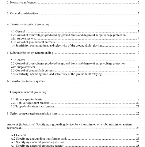
IEEE C62.92.5-2009 pdf download.IEEE Guide for the Application of Neutral Grounding in Electrical Utility Systems, Part V—Transmission Systems and Subtransmission Systems
4. Transmission system grounding
4.1 General According to IEEE Std 1313.1-1996, the AIEE Committee Report, “Application Guide on Methods of Neutral Grounding of Transmission Systems,” [B2] 4 and IEEE Std 32-1972, grounding of the transmission system neutral is an established practice, and in the design of a new system or the revamping of an old one, the question is not “should the neutral be grounded,” but rather “what means of grounding is best suited to the application.” In systems operating at 115 kV and above, there are strong economic reasons encouraging the use of effective grounding, as explained in IEEE Std C62.92.1-2000.
The most significant factors are insulation costs and the lower cost per kilovoltampere of transformers. Neutral grounding affects insulation requirements in two ways. First, the use of effective grounding controls temporary overvoltages due to ground faults at lower levels than those obtained with other classes of grounding. Second, effective grounding permits the use of lower-rated surge arresters, thereby providing better protection of the insulation against surge voltages. Many transmission systems consist of multiple voltage levels in which new higher voltage lines are overlaid on an older, lower voltage system. The different voltage levels are usually interconnected through autotransformers.
This type of arrangement generally requires that both of the voltage levels be effectively grounded; otherwise, faults on the higher voltage system could impress excessive temporary overvoltages on the lower voltage system.
Two-winding transformers could be used if it were desired to have one of the voltage levels non-effectively grounded, but the transformer cost differential encourages the use of autotransformers and effectively grounded systems.
The use of three winding transformers is another method to connect two transmission systems of different voltages together, or to connect a transmission system to a subtransmission system.
The transformer can have a wye-delta-wye connection, with the transmission system connected wye and either solidly grounded or grounded through a low impedance. Thus, the transformer is a ground source for both transmission systems. The delta winding may be left idle or may be used to provide station service, to supply capacitor or reactor banks, or to supply a distribution system. This winding should be protected against surges if the terminals of the delta are brought out external to the transformer tank. Transmission systems are normally connected to generating systems by means of a delta-wye connected transformer bank with the generator side connected in delta and the transmission system connected grounded-wye.
This connection provides a ground source for the transmission system. It also reduces the magnitude of ground-fault current in the generating system.
4.2 Control of overvoltages produced by ground faults and degree of surge- voltage protection with surge arresters There are two components of voltage or overvoltage in electrical systems when a system ground fault occurs or when a circuit breaker or a switch operates in clearing the ground fault. One of these is the temporary overvoltage or fundamental frequency overvoltage, and the second is the natural frequency voltage, usually of short duration, that is superimposed upon the temporary overvoltage. Since total voltages are of greater interest, the sum of the temporary overvoltage and the natural frequency voltage is commonly used. This sum is referred to as the transient overvoltage.
4.2.1 Temporary overvoltage (TOV) and arrester rating The ultimate surge voltage protection is obtained through arrester voltage ratings as low as system grounding conditions will permit during normal and abnormal system conditions. Initially, however, when the surge arrester was adopted as the basic protection device, the equipment design (coordination of major insulating structures) assumed that an “ungrounded neutral” or “100% rated” arrester would be used, unless otherwise specified (IEEE Std C62.11-2005).IEEE C62.92.5 pdf download.IEEE C62.92.5-2009 pdf download
IEEE C62.92.5-2009 pdf download

Leave a Reply