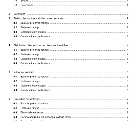
IEEE C37.32-2002 pdf download.American National Standard for High Voltage Switches, Bus Supports, and Accessories Schedules of Preferred Ratings, Construction Guidelines, and Specications
2 Definitions
The definitions of terms contained in this document, or in other standards referred to in this document, are not intended to embrace all legitimate meanings of the terms. They are applicable only to the subject treated in this standard. An asterisk (*) following a definition indicates that at the time this standard was approved, there was no corresponding definition in C37.100. Refer to C37.100 for additional definitions.
2.1 outdoor switch: Switches designated for operation outside buildings or enclosures. Outdoor switches may be exposed to the weather. Outdoor switches experience no restriction of heat transfer to the ambient.
2.2 indoor switch: Switches designated for operation inside buildings or weather-resistant enclosures, which do not restrict heat transfer to the ambient.
2.3 enclosed switch: Switches designated for operation within a housing restricting heat transfer to the external medium.
2.4 station class: A descriptive term used to denote application or restriction or both to generating stations, switching stations, substations, and transmission lines.
2.5 distribution class: A descriptive term used to denote application or restriction or both to that part of an electric system between the substation and the customer.
3 Station Class Outdoor Air Disconnect Switches 3.1 Basis of preferred ratings The ratings of station class outdoor disconnect switches shall be based upon the definitive conditions specified in C37.30.
3.2 Preferred ratings
3.2.1 Voltage and current The preferred voltage, continuous current, and withstand current ratings at the rated power frequency of 50 or 60 Hz shall be in accordance with tables 1, 2, and 3. 3.2.1.1 Short-time withstand current duration The preferred short-time withstand current test duration is 1, 2, or 3 seconds with allowable I 2 t variations given in C37.34.
3.2.1.2 Peak withstand current duration The preferred peak withstand current test duration is 167 milliseconds.
3.2.2 Ice breaking ability If an outdoor switch has an ice breaking rating, the preferred ratings shall be 10 mm (3/8 inch), and 19 mm (3/4 inch). A switch that has successfully passed the ice test and is rated for a given thickness of ice is also rated for lesser thickness.
3.2.3 Mechanical operations
The preferred mechanical operation rating shall be 1000 operations: 900 close-open cycles without terminal loading and 100 close-open cycles with terminal loading as specified in C37.34. Refer to table 17 for rated control voltages for motor-operated switches and C37.34 for number of operations at minimum and maximum control voltage.
3.2.4 Terminal loading
The preferred mechanical terminal loadings shall be in accordance with table 4.
3.3 Dielectric test voltages
3.3.1 Energized parts to ground
Outdoor switches in either the open or closed positions shall withstand the voltages specified in table 1,columns 2, 3, and 4. See note 1 of table 1 and table 2 for switching impulse ratings.
3.3.2 Open gap withstand The air gap of fully open outdoor air switches shall withstand voltages that are 1.10 times the rated lightning impulse dry withstand and the power-frequency dry withstand voltages given in columns 2 and 3 of table 1. For switches rated 362 kV and higher, the open gap shall also withstand the switching impulse voltages specified in table 2. Station class outdoor air switches having solid insulation material across the open gap shall withstand 100 percent of the voltages given in table 1 columns 2, 3 and 4.
3.3.3 Corona and radio influence test voltage limits Switches rated 123 kV and higher when tested under dark conditions at the voltage levels specified in table 1, column 5 shall be free of visible plumes or spikes. The limits of radio-influence voltage are given in column 6. Refer to C37.34, and NEMA 107 for testing procedures.
3.4 Construction specifications
3.4.1 Insulators Insulator units shall have electrical characteristics and leakage distance values equal to or exceeding those listed for equivalent insulation in C29.8 or C29.9. Refer to C37.35 and IEC 815 for insulator creepage distance considerations under contaminated conditions. Insulators shall have sufficient mechanical strength to withstand applicable operating forces, including magnetic forces produced by the rated peak withstand current of the switches for which they are supplied, as specified in table 3.
3.4.2 Arrangement and size of bolt holes in terminal pads Bolt hole centerlines in terminal pads, when used, shall be as shown in figure 1. Holes shall accommodate bolts that are ½ inch (12 mm) in diameter.IEEE C37.32 pdf download.IEEE C37.32-2002 pdf download
IEEE C37.32-2002 pdf download

Leave a Reply